TFRPM01D - RPM measuring device
Revolutions per minute measurement device for UAV. It is designed to direct connection to the Pixhawk controller (CUAV V5+ for example) through a standard I²C connector. The device is supported by PX4 firmware. The input of the meter is supposed a pulse signal from an optical encoder, hall sensor, etc. The pulses are counted during a predefined constant interval. The hardware is intended to be used for helicopter and autogyro rotor RPM measurement, but its counting capability is up to 20 kHz therefore it should be used for propeller or engine RPM measurement.

Where to get it?
ThunderFly RPM counter is commercially available from ThunderFly s.r.o., write an email to info@thunderfly.cz or shop at Tindie store.
Main Features
- Schmitt trigger input to shape a non-uniform signal from the RPM sensing element.
- Offload the flight controller’s MCU, by self-counting and storing the number of counted pulses in I²C accessible internal memory
- Input status LED indicator - optionally visible at daylight for easy debug of mechanical configuration
- Short circuit protection on the probe connector
- Pass-trough I²C connectors to allow a daisy chain of additional or multiple sensors
- Highly robust and repairable design.
Parameters
| Parameter | Value | Description |
|---|---|---|
| Pulse frequency range | 0 - 20 kHz (equal high and low periods) | Maximum RPM value varies by pulse number per revolution |
| I2C Connector | 2x 4-pin JST-GH | Connected in parallel |
| RPM connector | 3-pin 2.54mm pitch header | Internal 22k Ohm pullup resistor |
| I2C address | 0x50 default | By switching JP1 possible change to 0x51 |
| I2C SCL clock frequency | Max 100 kHz | Operation on 400 kHz is possible, but unreliable |
| Operating and storage temperature | −20°C to +40°C | Limited by case material |
| Operational input voltage | +3.6V to +5.4V | Overvoltage internally protected by Zener diode, Undervoltage is not treated |
| Mass | 4g PCB + 8g case | Printed case gcode included in docs |
| Dimensions | 23.5x42x12.5mm / 37.5x19mm | Case / PCB |
| Weather resistance | IP40 | External connectors fully occupied |

The 3Pin probe connector is powered from the I²C bus through an RC filter which limits current and voltage spikes to the sensor probe. Therefore sensor is resistant to short circuits at the probe connector power.
The two I²C Pixhawk JST-GH connectors are interconnected. This feature allows easy nesting with other I²C devices to a single Pixhawks I²C port.
Connection to the Pixhawk autopilot
The I²C interface connectors respect the Pixhawk connector standard. The signal and color coding of the connector and supplied cable are described by following table (ThunderFly color scheme):
| Signal | Pixhawk Color | ThunderFly color |
|---|---|---|
| +5V | Red |  Red Red |
| SCL | Black |  Yellow Yellow |
| SDA | Black |  Green Green |
| GND | Black |  Black Black |
The conductor colors in the cable are different from the Pixhawk standard to increase the visual distinction between multiple cables in the UAV.
Wiring cable
To improve I2C bus reliability, the supplied cable is specifically twisted by following the scheme
- 10 turns for each pair SCL/+5V and SDA/GND per 30cm cable length
- The two pairs are turned again by 4 turns of pairs per 30cm cable length.
These special cable conductors’ winding method greatly improves the signal integrity by minimizing the crosstalk between the SDA and SCL signals.
I²C Address Configuration
By default, the TFRPM01C sensor is manufactured with a 0x50 I²C address. This address is possible to change to 0x51 by altering the JP1 solder junction. The junction connection to GND needs to be cut by knife and then soldered to the opposite side Vcc.
The default configuration of the junction corresponds to the following picture, where the center pin is connected to GND by copper trace.

Mounting options
The device is designed to be mounted with or without a plastic case. The 3D-printed case is intended to be adjustable to particular sensor mount options. The supplied variant of the 3D-printed case supports two mount options:
- By default the case could be mounted by the screw on a flat surface (the original screw needs to be replaced by a longer one)
- The second option is the use of double-sided adhesive tape or reclosable fastener stuck on the side of the TFRPM01 case.
PCB dimensions
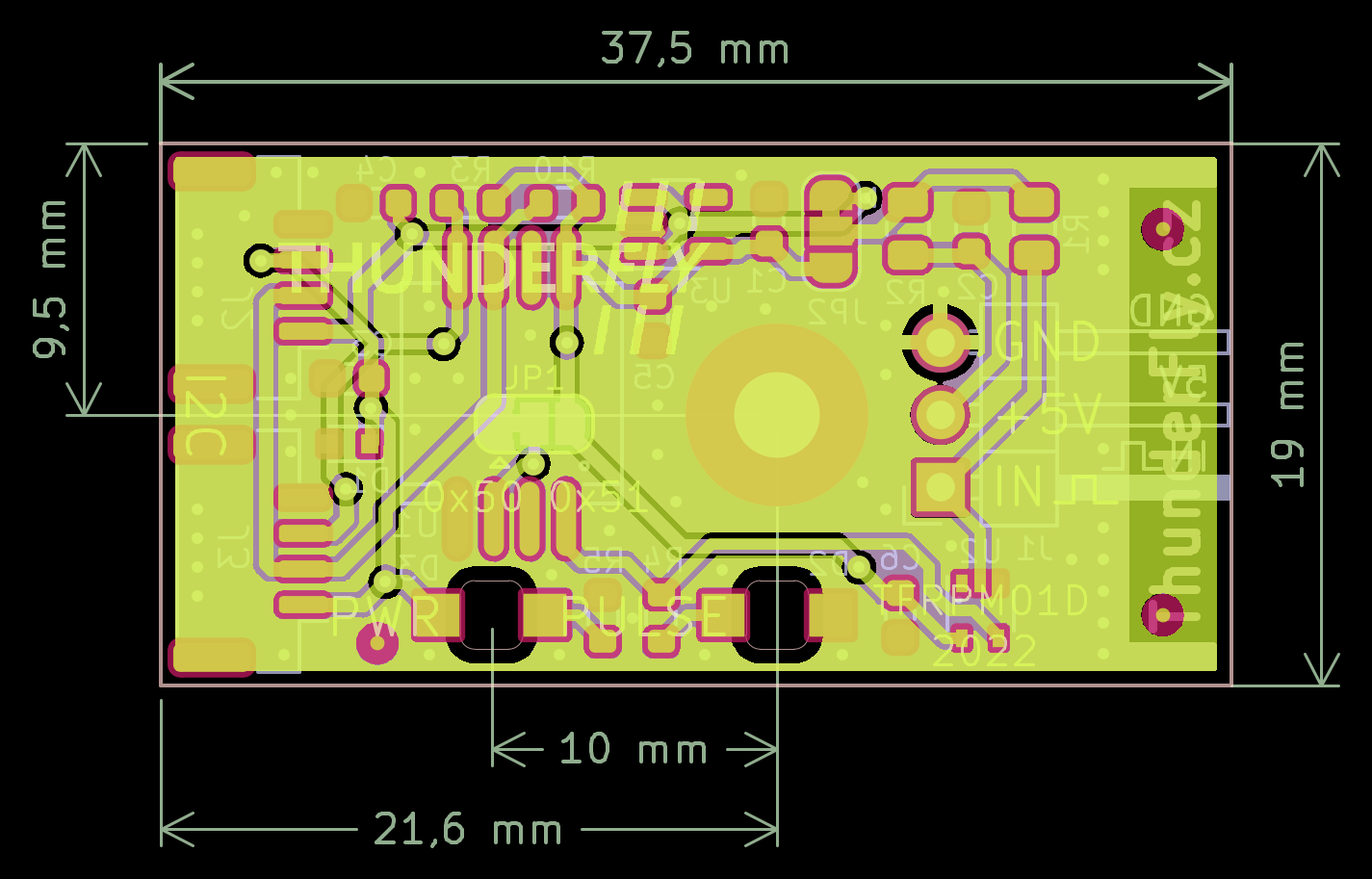
The PCB is designed to be mounted on a flat surface by a center screw hole. The supposed screw diameter is metric 3mm e.g. DIN 912 M3 Hexagon socket Head Cap Screws. The A2 stainless steel with non-ferromagnetic properties is used for the screw and nut to avoid influence on UAV’s magnetometer.
Sensor probe selection
The counter could be used with multiple types of sensor probes. The most used one is a Hall effect probe. The magnetic probe is ideal for harsh environments, where dirt, dust, and water can contact the sensed rotor. The disadvantage is, that mounting of the magnet is required for proper sensor work.

The probe should be connected to the sensor board as follows (- Black, + Red, Pulse Blue)

The correct connection of the probe could be checked by the magnet, and the PULSE LED switch on and off according to magnet presence. The sensor board needs to be powered from at least one I²C port during the test.
The sensor could also be used with other probe types. We tested the se TFPROBE01, which combines the optical reflective sensor and magnetic hall-effect sensor in one device.
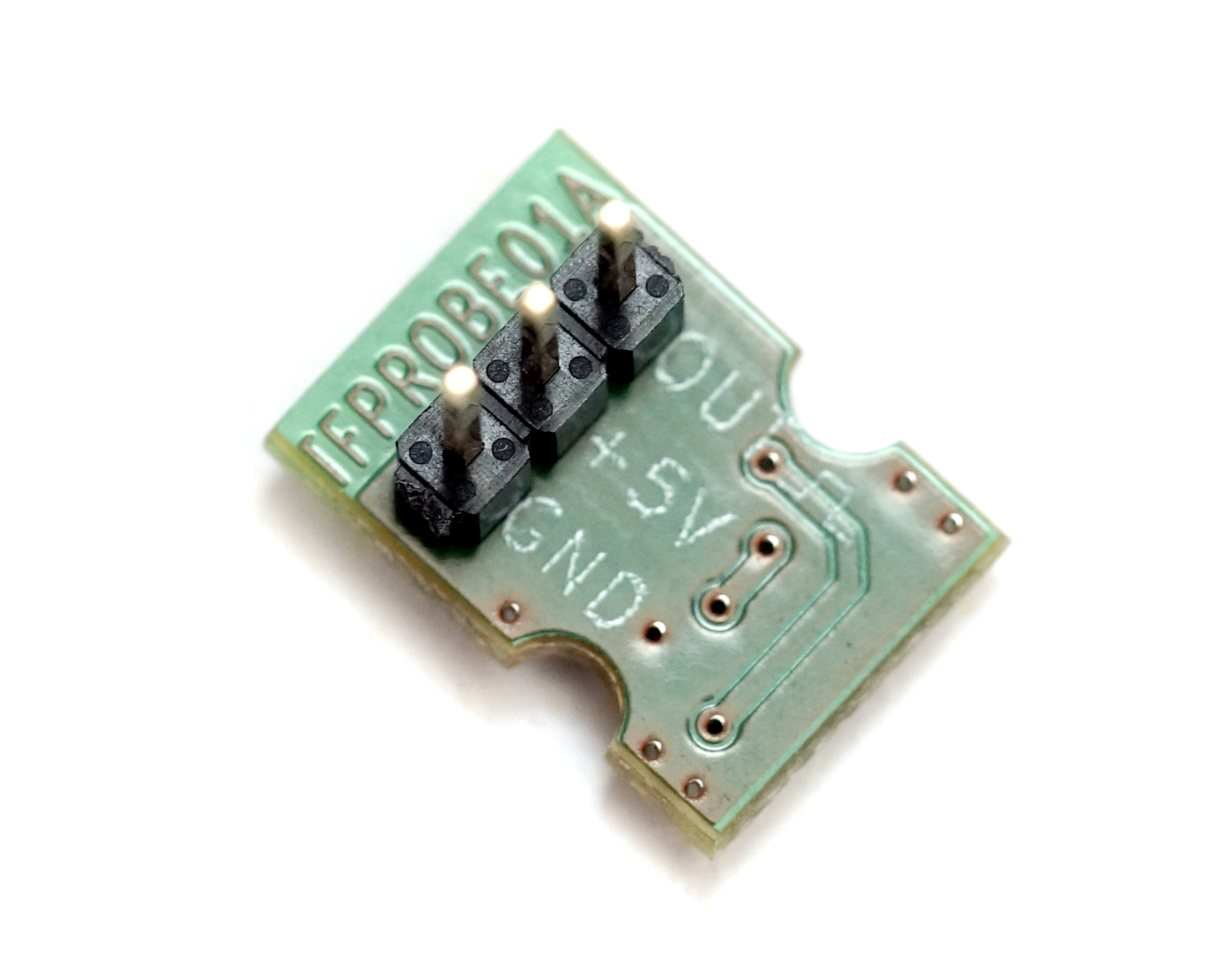
TFPROBE01A - Omnipolar magnetic and reflective optical sensor probe
The sensor is specifically designed for simple RPM measurement with the TFRPM01 sensor board. The probe consists dual sensing technique - optical or magnetic. Therefore the user should select the one most suitable for the application.
Magnetic Sensing
The magnetic Hall-effect sensor mounted on the probe board can sense both directions of the magnetic field. The strength of the magnetic field is a decisive parameter for the probe’s correct function. The magnetic flux is expected to be perpendicular to the sensor PCB surface. The detailed requirements of magnetic flux density are described in AH3572 datasheet page 4.
In magnetic sensing mode, it is recommended to cover the probe in a black shrinking tube. The covering blocks the potentially unwanted function of a reflective sensor.
Optical Sensing
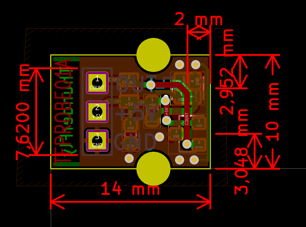
An optical sensor is sensitive to the infrared reflectance of material (usually a rotating disc with marks). To details see the VCNT2020 datasheet page 2 it should be noted that the optical sensor needs highly contrast sulface in IR spectrum. It is also sensitive to ambient sunlight and works correctly only on distances up to two millimeters.
TFPROBE Hardware specification
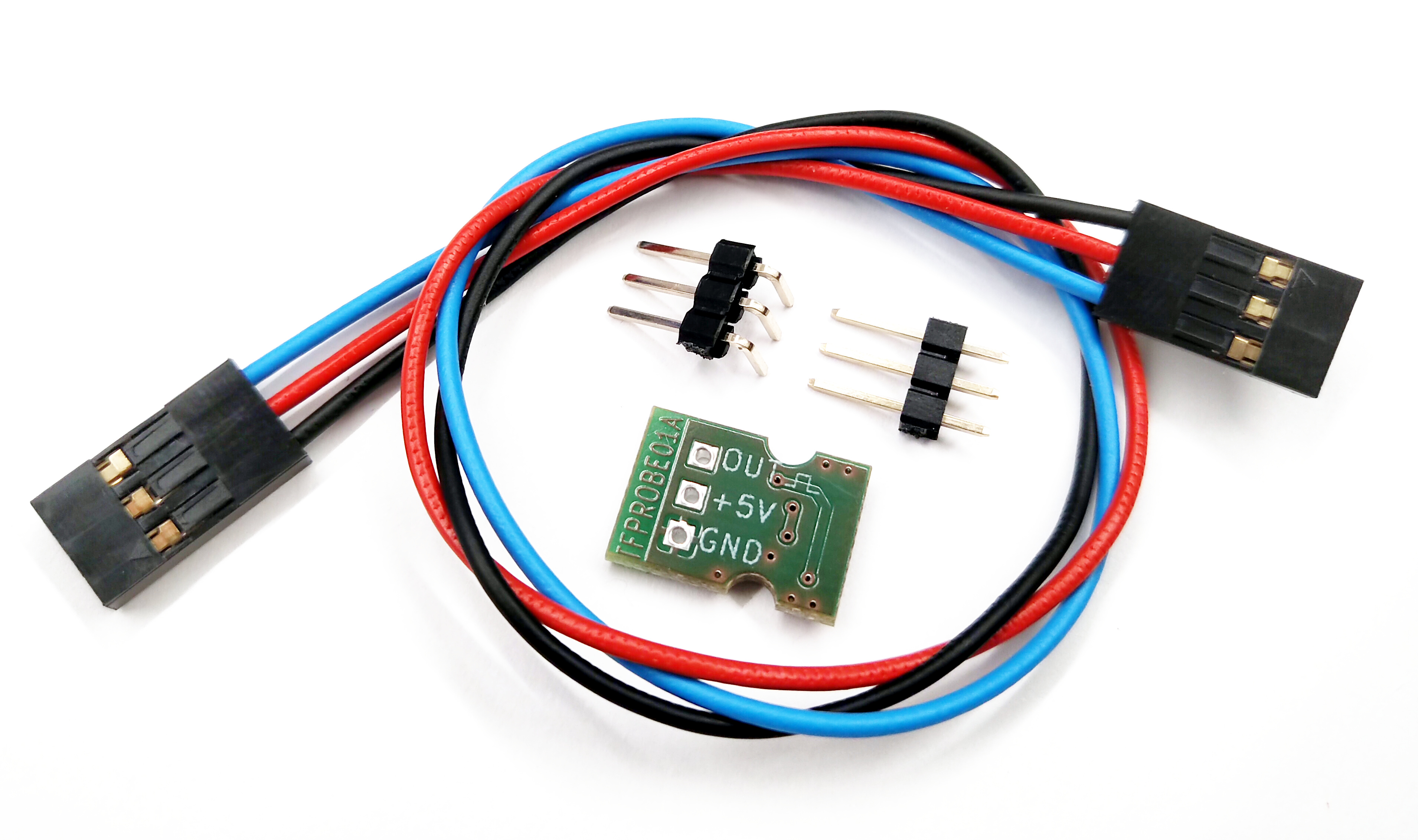
The TFPROBE01 is sold and shipped without a soldered header, because its orientation may depend on the customer’s use. Connecting cable and two headers (one straight and one right-angled) are included.
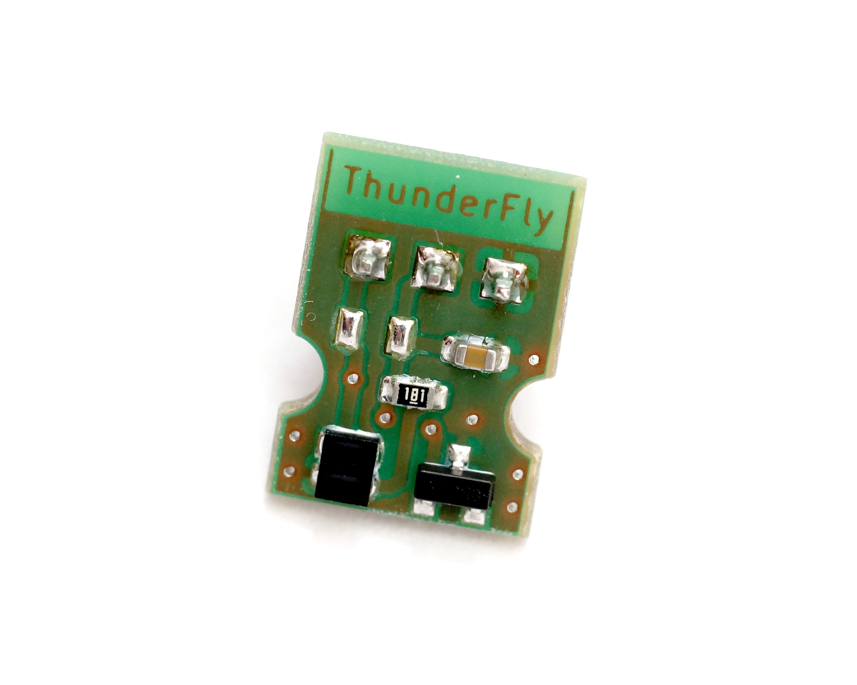
Optical and magnetic probe positions on PCB
Use of other sensors
Technically TFRPM01 could be used by every probe with pulsed output with amplitude in the range of 0 to +5V. However, the TFRPM01 sensor needs to match the input parameters to certain probe types. The default configuration is reflected in the following schematics.
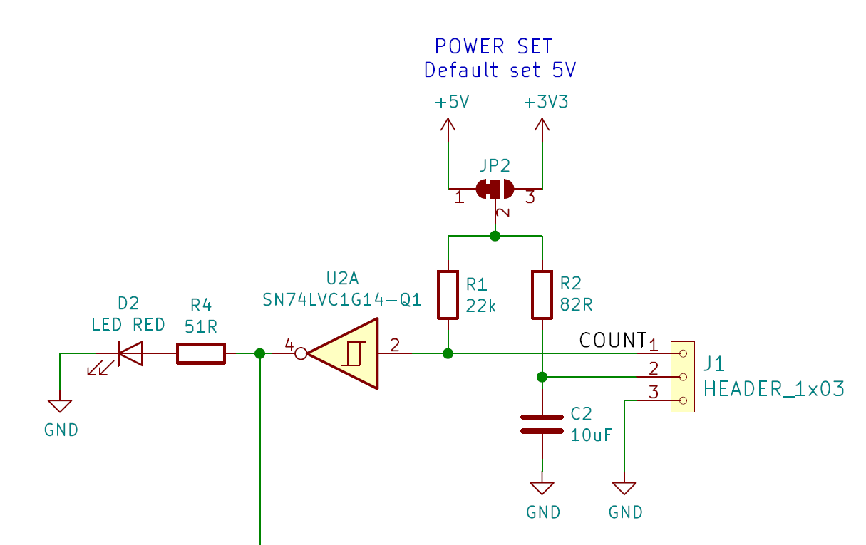
As can be seen from the schematics the default probe power selection is +5V, protected by resistor R2 to about 61 mA short-circuit current. The pull-up resistor R1 with a default value of 22 kOhm is quite hard and it is generally unsuitable to most optical probes with open-collector outputs. Therefore the resistor R1 should be interchanged to a more suitable (usually increased) value. It is depending on the selected material for the optical sensor this value might need further fine-tuning. (The specific resistor value could be requested during the order process in case of ordering a larger quantity).
Software configuration
The TFRPM01 revolution counter is currently supported by PX4 firmware only. (Ardupilot pull requests are welcomed) After proper connection of the sensor with the sensing probe to an I2C port (Except port I2C3) of PX4-based autopilot you should follow instructions to PX4 software setup. After proper setup, you should get an uLog containing the RPM logged during the flight. Here is an example of rotor RPM captured during the flight of TF-G2 autogyro. The graph is rendered by flight_review.

FAQ
What about the measurement resolution of the RPM?
RPM measurement resolution depends on pooling interval and the number of pulses per revolution.
RPM is calculated from measured values (pulses per interval) as follows
Therefore the resolution of measured RPM is the follows:
Where:
- N is pulses per revolution
- τ is the pooling interval in seconds
- Nc is pules counted during the measurement pooling interval
- Res is the absolute resolution of measurement in +/- RPM
Therefore the absolute resolution of the sensor is independent of the current RPM measured and remains constant depending on sensor configuration, however, relative resolution increases with the RPM measured. The absolute resolution strongly depends on the length of the pooling interval (a longer interval gets better resolution). The resolution also increases with the number of pulses per revolution, where more pulses per revolution give better RPM resolution. Related terms like precision and accuracy are more difficult to analyze because depend on hardware and firmware versions of Pixhawk, but these errors could be neglected in the usual use cases.
Does it connect to RPM output from ESC?
Generally yes, the TFRPM could be connected to revolution output from an ESC in case of output logic confirms to 5V TTL. The limitation is the RPM resolution here because many ESCs get one pulse per revolution. See the formula above for an explanation.
Could be used for internal combustion engines?
Yes, it could measure the RPM of the IC Engine. However, it needs a pulse signal to count the rotation speed. The pulsed signal could be either obtained either from Electronic control unit (ECU) or from an Optical or magnetic probe mounted on the proper location of the engine unit. Direct connection of TFRPM to ignition or sensing coils is not possible without signal conditioning, because the voltage of signals coming from coils will likely destroy the TTL-based RPM input of TFRPM. Required signal conditioning could be realized by a resistor network in many cases. Contact ThunderFly s.r.o. in case you need professional support.